


High levels of partial discharge (PD) were detected over several years on the main electrical components (Generator, Step-up transformer, HV Connections) of a 660MW thermal generating unit in the UK. The significance of the PD, both in terms of the levels observed and the wide area of the plant over which the PD could be detected raised serious concerns about the condition of this key generating asset and the potential for unplanned downtime and equipment damage.
Offline electrical testing, performed during the same time as the PD was being identified, presented no immediate indication of insulation degradation – further complicating investigation efforts. The unit in question plays a vital role in the UK power grid, providing nearly 1% of demand and essential ancillary services. Unplanned downtime is extremely undesirable. The PD signals were detected across multiple assets and locations, including electrically unconnected equipment nearby, complicating source identification.
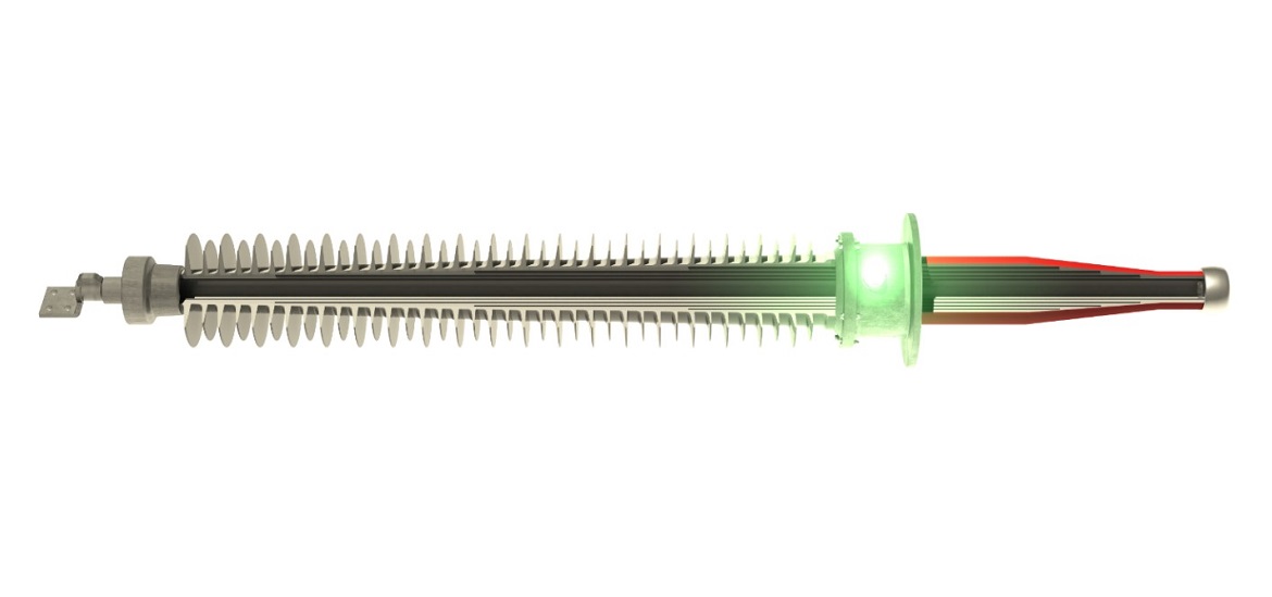
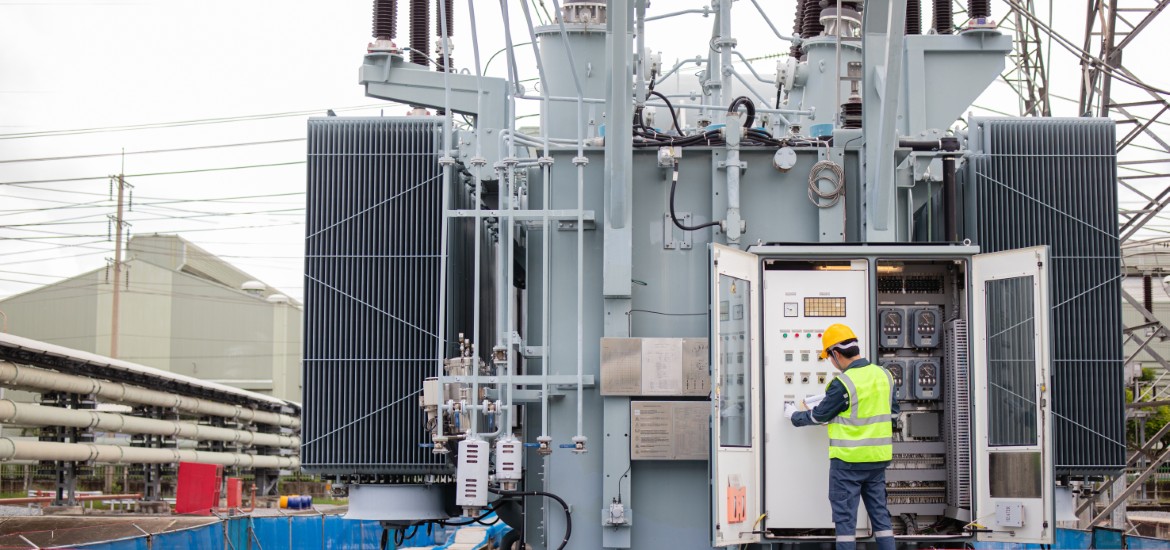
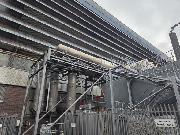
- Background: The 660MW unit in question uses a steam turbine to drive a generator with a terminal voltage of 23.5kV. This voltage is then stepped up further to 400kV via a generator step-up transformer for export into the UK transmission network. A further transformer, referred to as a unit transformer, steps voltage down from 23.5kv to 11kv to feed internal auxiliary power. The Generator & GSUT/Unit transformers are linked by means of a common 23.5kV iso-phase busbar (IPB) arrangement consisting of aluminum conductors supported on a mixture of composite and porcelain insulators. The IPB itself is not fitted with any PD monitoring equipment, but the Generator is fitted with coupling capacitors on both the line and neutral ends of the stator, and both transformers are fitted with in-tank UHF probes and High Frequency CTs on the neutral terminals.
- Initial discovery of high PD levels: Routine online monitoring, using both a fixed condition monitoring system and handheld measurement devices started in 2018. On this particular generating unit, measurements on both systems revealed abnormally high levels of PD on the generator, generator transformer, and unit transformer, with no correlation to operational parameters and no deterioration over time. Spot measurements taken on plant in the local area but not directly connected to the same electrical system (for example, 11kV switchgear installed nearby) also presented the same PD signature and severity. Various operational switching scenarios and differing plant configurations were tested to determine the effect on PD signatures, but all such efforts resulted in a sustained high PD level.
- Extensive inspections during outages: During Major outages performed in 2020 and 2024, detailed visual inspections, both internal and external, and offline electrical testing (PD mapping, Tan Delta, insulation resistance) of all the key generator & transformer assets, as well as all IPB components were performed. This testing found no evidence of insulation faults or deterioration despite persistent PD signals. Comparison of results obtained in 2020 & 2024 both on the affected generating unit and with other adjacent generating units of the same design, age, running regime and construction gave no evidence of plant condition deterioration or potential failure. No ‘red herring’ results could be identified on any of the offline inspection or test results.
- Isolation and withstand testing of IPB conductors: During the 2024 outage, power frequency AC withstand testing was performed on the IPB conductors of the affected unit. Such testing is typically preceded with a DC insulation resistance test to prove suitability for AC testing. In the case of this unit, DC insulation resistance (IR) tests passed with no issue and high resistance values. However, during application of the AC voltage to the ‘C’ phase IPB conductor, a trip occurred at approximately 4.5kV RMS. Following the trip, further DC IR testing was performed at a voltage higher than that which caused the trip during AC testing, but this continued to present extremely high IR values to ground, suggesting the conductor was clear of earth. Further AC test attempts again resulted in repeated tripping at the same voltage level which was much lower than that to which the conductor is subjected in normal service.
An alternative AC test set, with a functionality to ‘Burn on Arc’ was then obtained and the AC test repeated. The previous trip level (circa 4.5kV) was passed without issue; however, at the level of approximately 7kV, which again is significantly below normal service voltage, significant instability of the output voltage value was observed on the test set. In conjunction with this, a high-pitched noise could be heard coming from within the IPB ductings, the intermittency of which corresponded to the pulses of the output voltage. This suggested a significant internal fault within the IPB.
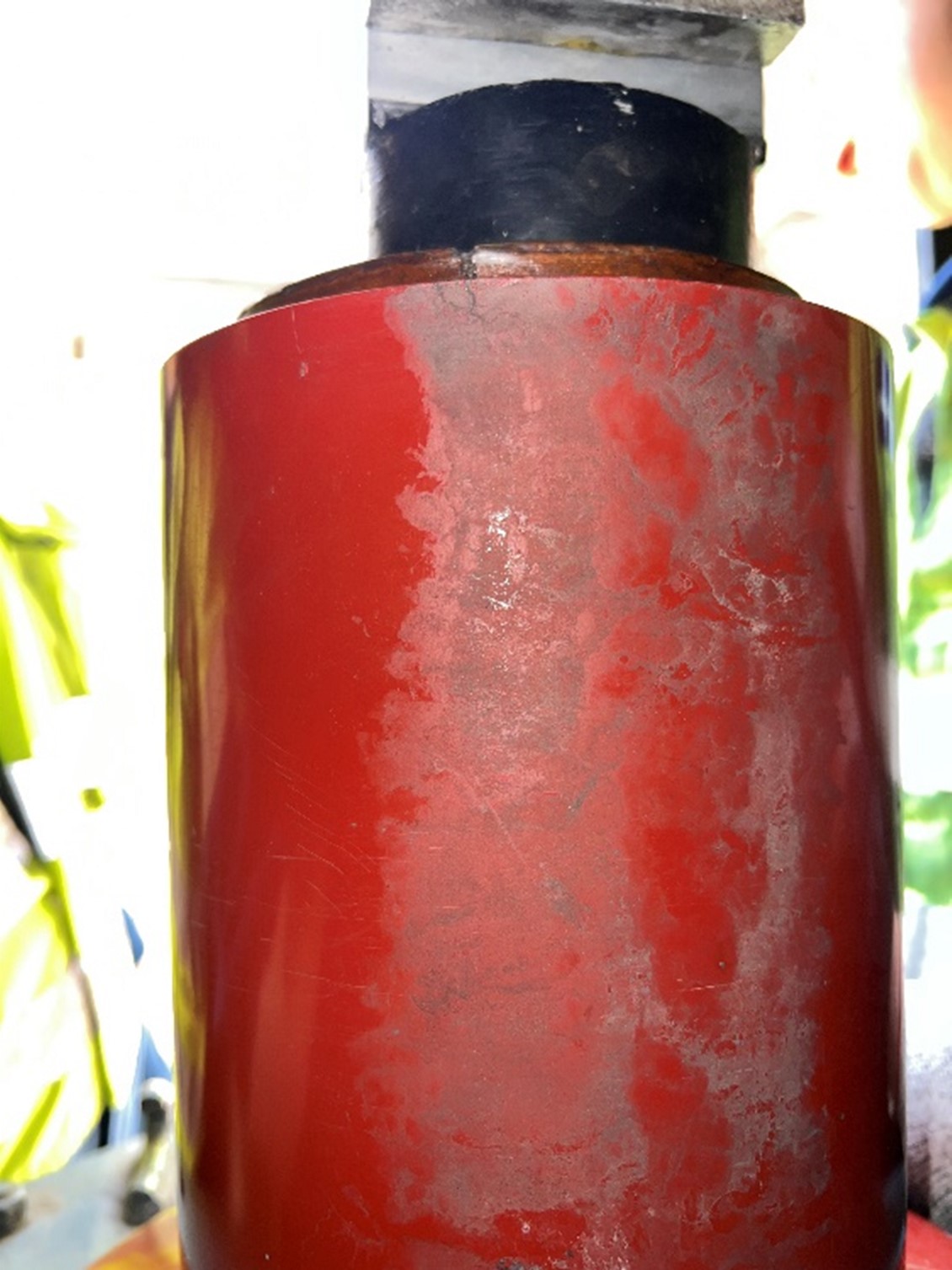
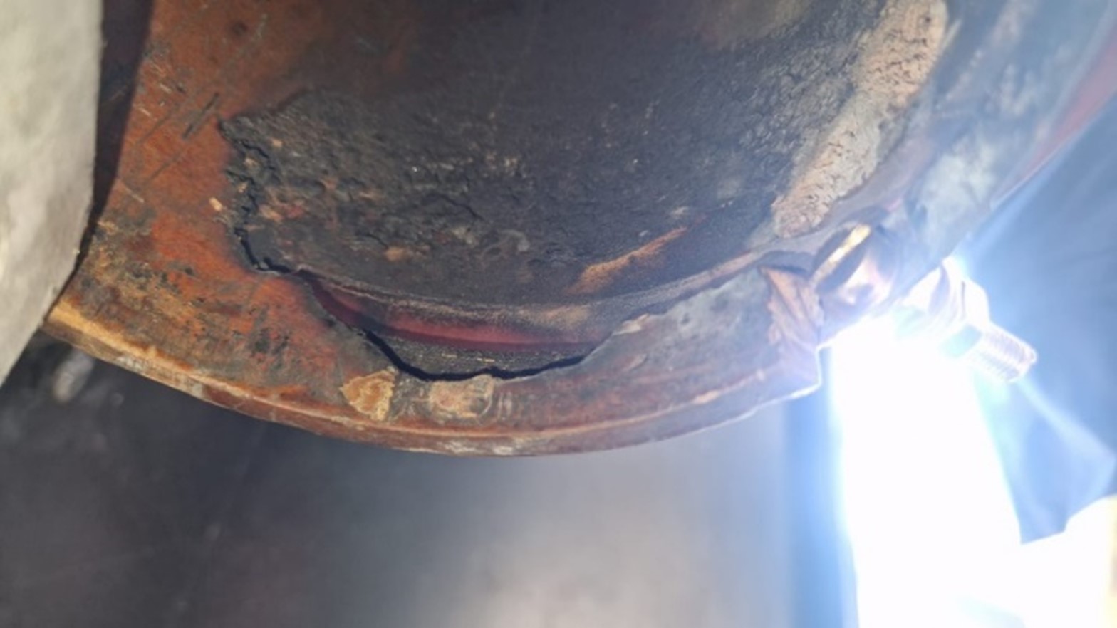
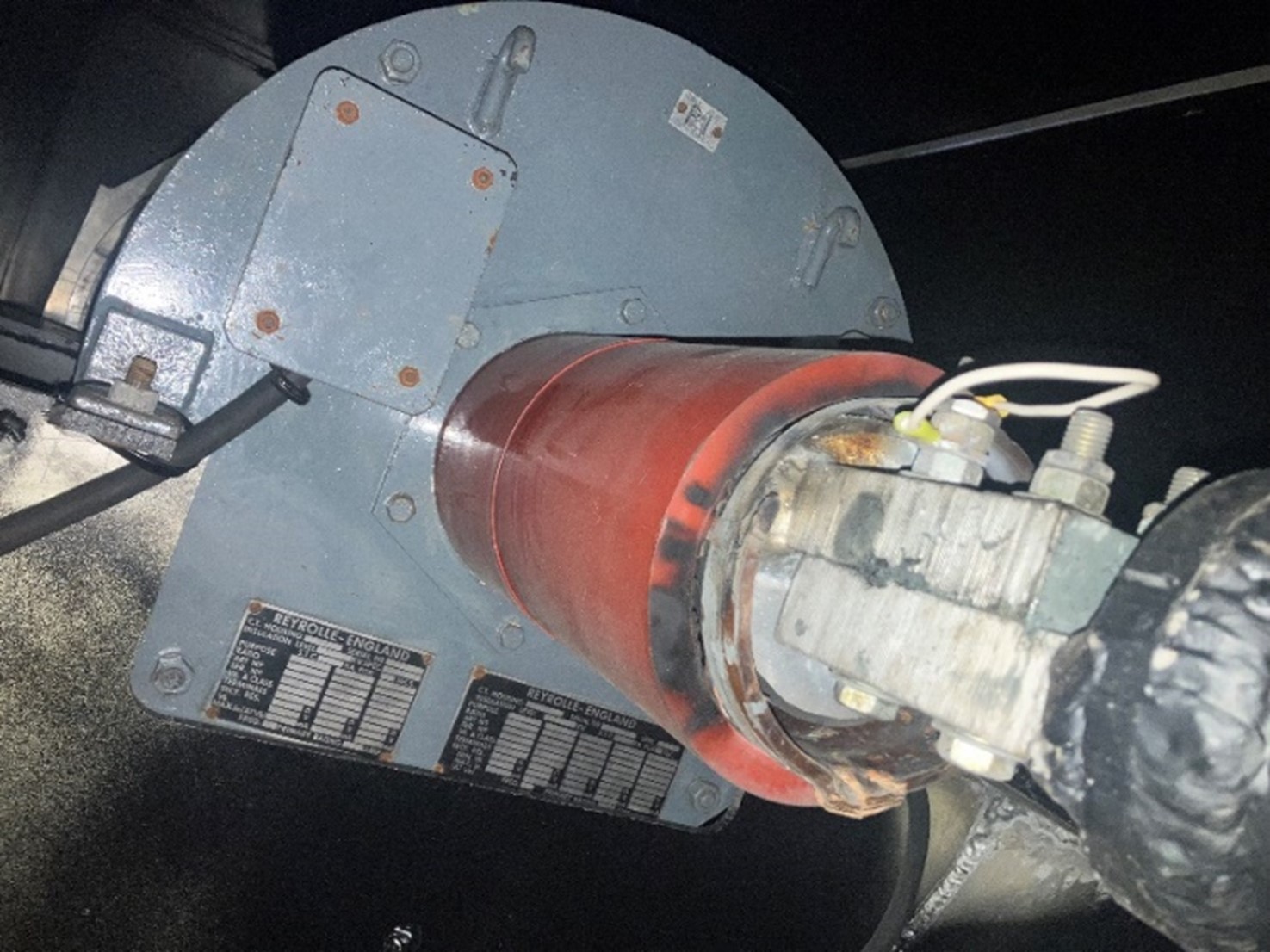
- Identification of the PD source: Following testing, full strip-down inspections of the IPB and all associated components were commenced. All conductors and insulators were found to be intact and clear of earth paths which could have explained the test flashover. Inspection behind an IPB CT cover presented a 50-year-old current transformer (CT) and evidence of extensive burning and insulation damage around the base of the CT unit. Further inspection within the CT chamber identified a broken equipotential bonding strap and severe insulation erosion (electrical treeing) and charring (See figs 1 & 2). The equipotential bonding strap is intended to bond the central HV conductor to the inner layer of the insulation tube within the CT, so as to avoid discharge across an extremely small air gap. Further inspection with the CT isolated from the rest of the IPB system presented the same results during AC testing (voltage instability & audible noise at 7kV), whilst the rest of the disconnected IPB system passed at rated voltage without issue. Loss of the equipotential bond had resulted in excessive damage & charring to the inner liner of the insulation, as well as significant electrical erosion on the outer composite insulator (see figures 3 – 5) The failed bonding strap was identified as the source of the persistent PD. 9
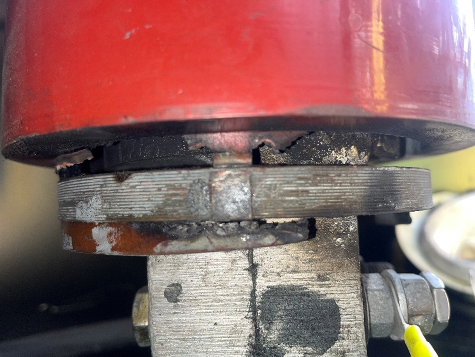
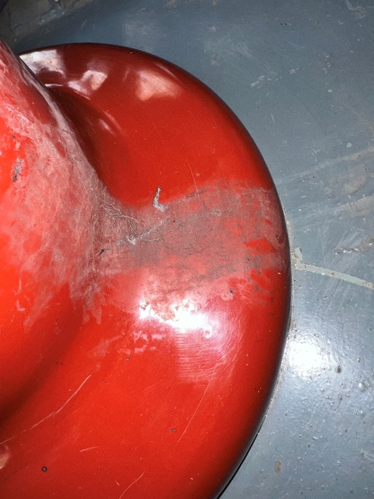
Figures 1 & 2 – IPB Mounted Current Transformer (CT) showing evidence of damage to equipotential bonding ring, inner insulation sleeve and tracking marks (treeing) in composite insulator
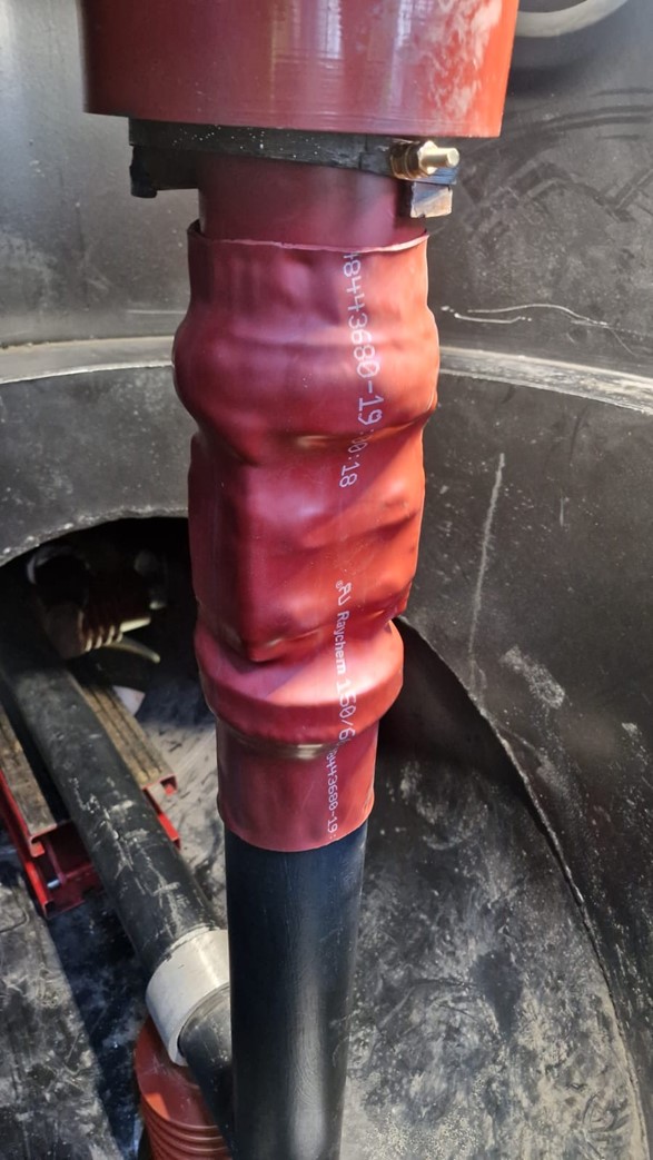
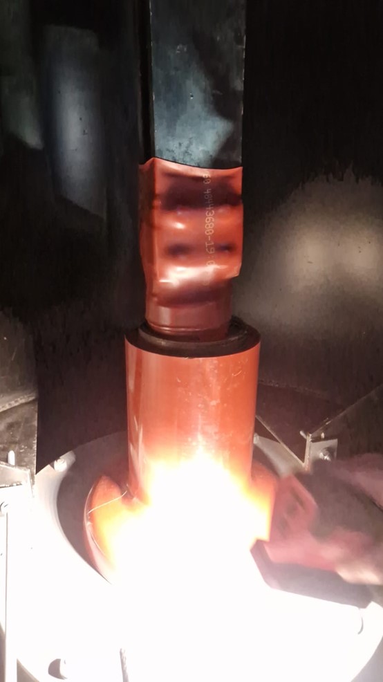
Temporary repair implemented: Due to obsolescence and lack of spares, replacement units were unavailable either locally or within acceptable timelines from national or international manufacturers. A temporary repair was therefore made by wrapping the inner conductor with high voltage busbar heatshrink tubing to effectively insulate the damaged CT resin sleeve and use the heatshrink tubing as the primary insulation, allowing the unit to return to service safely. See Figures 6 & 7.
Post-repair PD reduction: Subsequent PD measurements post repair showed a significant reduction to expected levels consistent with other units, with no further deterioration observed, validating the repair effectiveness. In the longer term, this then provided the necessary time and space required to obtain replacement CT units as a permanent replacement scheme.
Lessons and implications: This case highlights challenges in detecting PD sources in complex operational plants, the value of online PD monitoring, and raises questions about handling unexpected condition monitoring results on aging assets. It also led to updates in maintenance and inspection policies to mitigate future risks.

Tony McGrail is Doble Engineering Company’s Solutions Director for Asset Management & Monitoring Technology, providing condi tion, criticality and risk analysis for utility companies. Previously Tony has spent over 10 years with National Grid in the UK and the US; he has been both a substation equipment specialist and subsequently substation as set manager, identifying risks and opportuni ties for investment in an aged infrastructure. Tony is a Fellow of the IET, a member of the IEEE, CIGRE, ASTM, ISO and the IAM, and is currently active on the Doble Client Commit tee on Asset and Maintenance Management and a contributor to SFRA, Condition Monitor ing and Asset Management standards. His in itial degree was in Physics, supplemented by an MS and a PhD in EE followed by an MBA.

Jamie Beardsall is a Lead Electrical Engineer with Drax Group, UK, with 10 years experience, focusing on asset condition assessment, mo nitoring and maintenance. Jamie has previ ously co-authored several technical papers on power generation assets and is a gradu ate of Staffordshire University. Jamie is a member of CIGRE working group A2/D2.65 – Transformer Digital twins and also sits on the UK Grid Code Review Panel.  

This article was originally published in the October 2025 issue of the Advanced Insulation Soulutions: Condition Monitoring for a Safer Grid magazine.
View Magazine