


INTRODUCTION
There have been many efforts to develop distribution transformers that generate less carbon emission, since energy losses in distribution transformers are estimated to account for around ~3% of the world annual electric power production. With many distribution transformers produced and installed broadly for various applications and locations, it is not only to consider losses reduction in operating transformers, but it is also critical to reduce energy consumption in the production of the transformers.
For high efficiency transformers with lower operating costs, manufacturers prefer to make low no-load loss (core loss) with high grade silicon steel or amorphous metal. Smaller core size also results in less load losses due to smaller coils, which enable the use of less winding and insulation materials in active parts which then contributes to use less energy in materials production. [1, 2, 3]
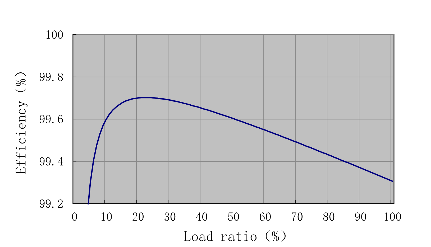
Amorphous metal is selected to generate low no-load losses even at high flux density of 1.6 T and to have less labor in cutting, forming and assembly with coils. Lower no-load losses at actual average load could result in significant reduction of carbon emission over lifetime of transformers. Amorphous vacuum pressure impregnated (VPI) transformer are designed to have highest efficiency at load factor between 10 and 50%, that fits well to actual average load in common distribution networks in most of the countries (Fig. 1).
With many distribution transformers produced and installed broadly for various applications and locations, it is not only to consider losses reduction in operating transformers, but it is also critical to reduce energy consumption in the production of the transformers.
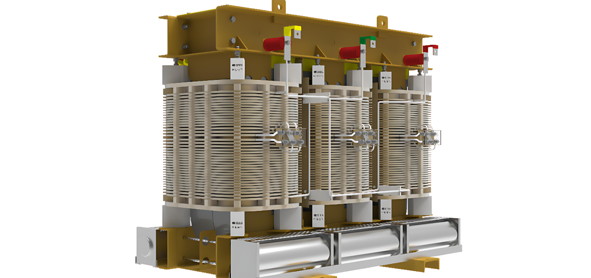
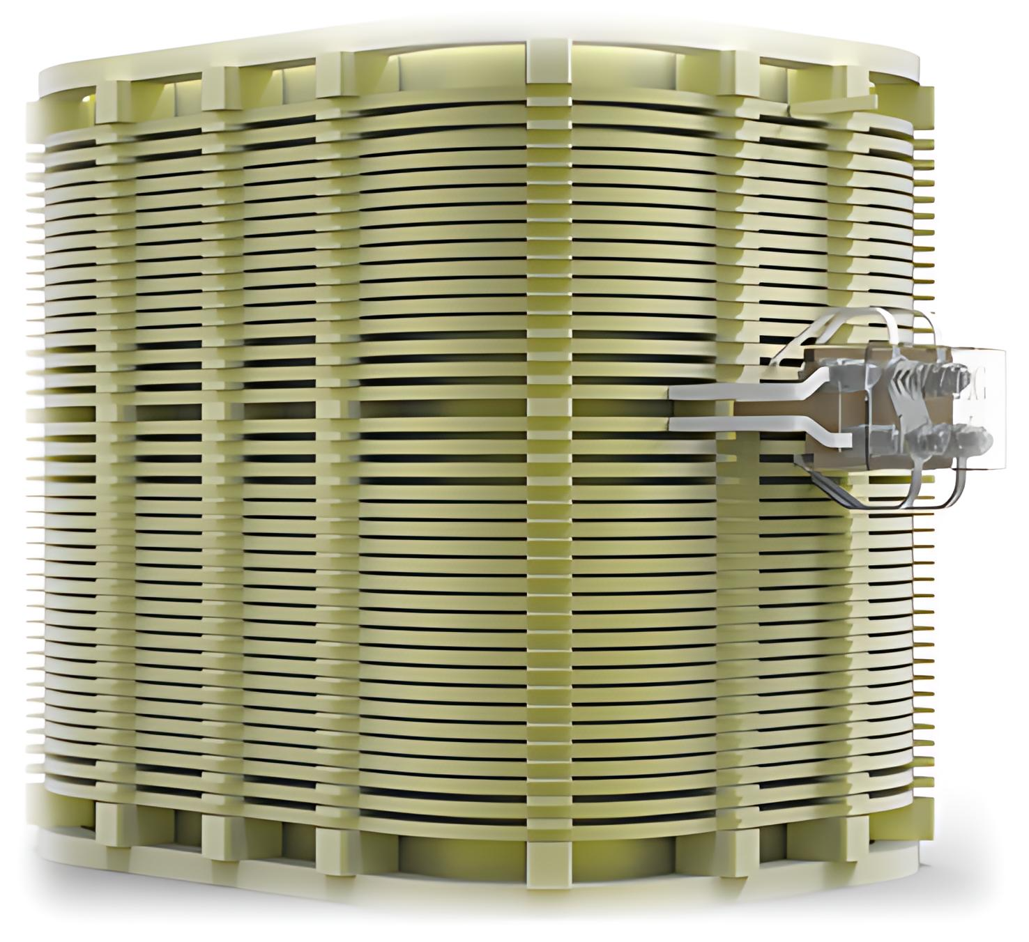
Core is made of amorphous alloy strip and adopts 3-phase and 3-leg structure. Cross-section of core leg is rectangular to reduce the length of transformers. Fig. 2 shows typical appearance of class H, VPI transformer; SGBH type (3-phase, open ventilated dry transformer with foil winding for LV coil and amorphous metal for the core).
Lower no-load losses at actual average load could result in significant reduction of carbon emission over lifetime of transformers.
VPI transformers that adopt 220°C insulation system have prolonged expected lifetime of more than 2 times as compared to dry-type transformers designed with insulation system in actual class H (180°C). Longer lifetime also contributes to saving materials in transformer production due to less demand for new transformers. This could reduce carbon emission significantly and could be a good reason when users choose green transformers. This paper focuses on core design with amorphous metal and insulation system used in VPI transformers to ensure low carbon emission and reliability during lifetime of transformers.
CORE DESIGN WITH AMORPHOUS METAL
- Amorphous metal
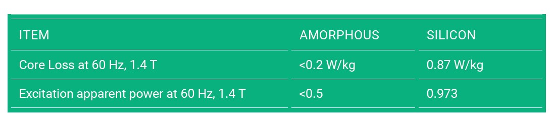
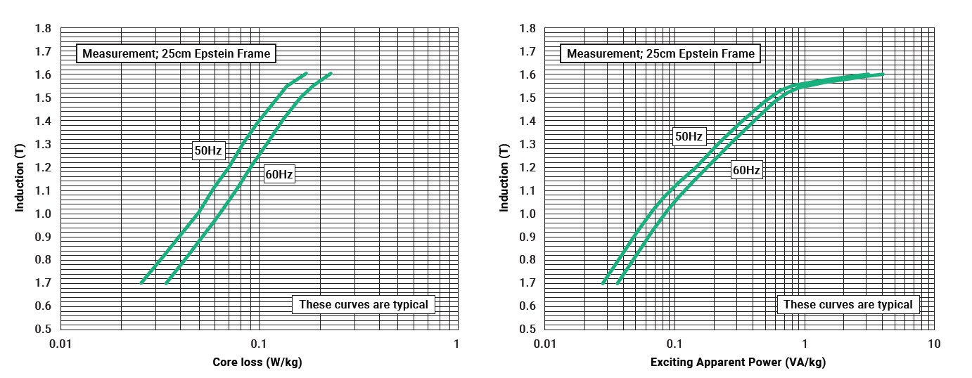
Basic elements of amorphous metal are iron, nickel, cobalt, etc. Its mole cular structure is in amorphous state to eliminate movement of magnetic domains, and its thickness is only 0.025 mm, which is 1/10 of the silicon steel. Table 1 presents comparison between amorphous metal and silicon steel. Iron loss of the amorphous metal is only 25% of silicon steel and excitation apparent power is only about 50%.
Fig. 3 shows graphs for typical no load loss and excitation apparent power of amorphous metal with thickness of 0.025 mm. 2. 3-phase core designs 2.1 Comparison of two core designs There are two designs for core structure: 3-phase, 5-leg core and 3-phase, 3-leg core (Fig 4).
2. 3-phase core designs
2.1 Comparison of two core designs
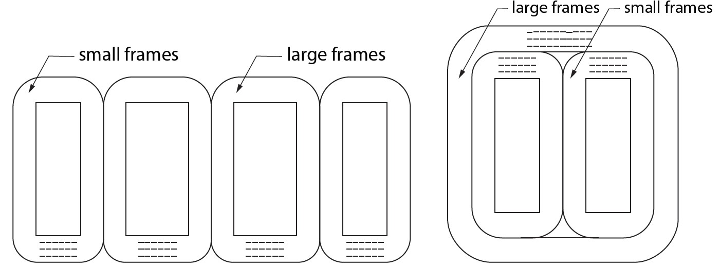
There are two designs for core structure: 3-phase, 5-leg core and 3-phase, 3-leg core (Fig 4).
- 3-phase, 5-leg core consists of two large frames and two small frames with side legs. Number of wound core assemblies can be increased accordingly to capacity of transformer, and the opening of iron core is at the bottom due to production process.
- 3-phase, 3-leg core consists of two small frames and one large frame. Number of core assemblies can be increased according to capacity of transformer. Core assembly is opened at the top. For assembly process with coils.
3-phase, 3-leg core has the following advantages:
- There are no side legs and transformer size is reduced by about 20%.
- Core weight is reduced by about 7%, cost is reduced by 6%-9% and no-load loss is reduced by 5%~8%.
- 3-phase, 5-leg core cannot be used for wye-wye connection because the third harmonic in core can pass through side leg to form flux path and the third order component in magnetic flux becomes large enough to distort sinusoidal wave. But the 3-phase, 3-leg core has no side legs and transformers can be connected for wye-wye vector group.
2.2 Magnetic circuit comparison
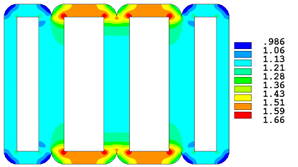
Analysis of flux density shows in Figure 5 the situation when voltage of phase B winding reaches its peak value. It shows that actual magnetic flux density in the core leg is close to design flux density but actual magnetic flux density in most areas of the yoke is higher than design flux density. This results in high no-load loss and sound level.
The same analysis was done for 3-phase, 3-leg core (Fig. 6). It shows that the situation when the magnetic flux density reaches its peak value. Flux density at the leg is only high around ends, and the excessive flux density on the legs and the yoke has been well suppressed.
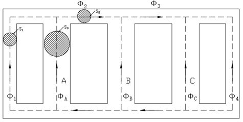
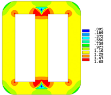
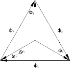
3-phase, 5-leg core consists of four independent core frames. When 3-phase magnetic flux is symmetrical sinusoidal wave, it can be drawn from magnetic flux distribution diagram in Fig. 7:
Φ1 = Φ2 = Φ3 = 1/√3ΦA = 0.577
Cross section area of side leg and upper yoke satisfies the following formula since the four frames of 5-leg core are completely independent:
S1 = S2 = 1/2S0 , from Φ1 = 1/√3ΦA Φ = SB
It can be concluded that
S1 B1 = 1/√3S0B0, thus B1 =2/√3B0 ≈1.155B0
Therefore, influence of saturated flux density should be considered in the design. In 3-phase, 3-leg core, the yoke and the legs have same cross section area and flux density can be increased by 1.155 times in theory. But actual increase is around 1.05 times. This can reduce the weight and cost of core assembly.
One of the most important factors affecting life of transformers is thermal aging of insulation materials. Thermal aging is related to a load rate, heat dissipation, ambient temperature, harmonics occurring during trans former operation. Rated hot spot winding temperature for insulation system in thermal class 180°C should be kept below 170°C (rated hot spot winding temperature from IEC 60076 12 [4]) to have life time of 180 000 h. But in the proposed design the conductor insulation for HV coils is made with aramid paper certified for 220°C by UL and the coils are impregnated with epoxy varnish by VPI process. Disk winding for HV coil and layer winding with foil for LV coil are very effective to reduce voltage stress and to have efficient heat dissipation that could slow down insulation degradation caused by dielectric and thermal stress.
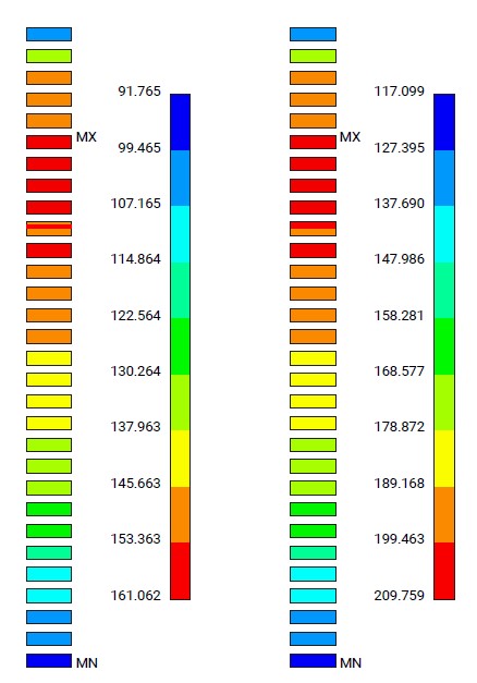
Temperature field analysis shows mapping of winding temperature distribution at Fig. 9. Hot-spot winding temperature was 161°C when the heat run test was done at rated capacity. If transformer is overloaded to 1.2 p.u. due to unexpected spike load or harmonics, the hot-spot winding temperature reaches 209°C. This would exceed permissible hot spot winding temperature of 170°C.
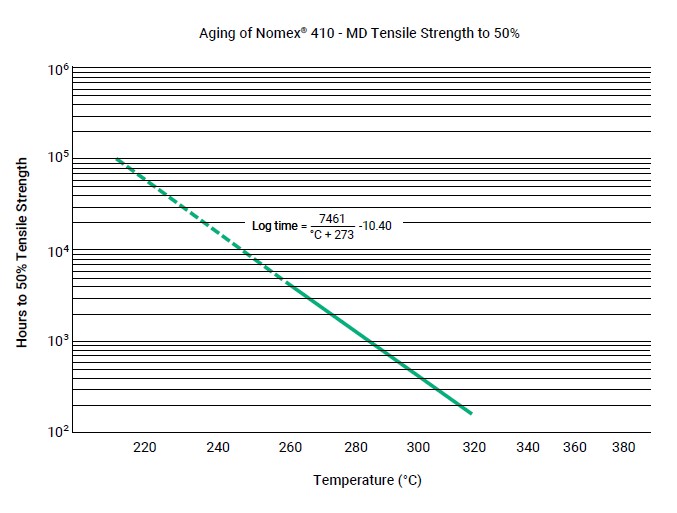
That is why the conductor is insulated with 220°C thermal class aramid paper, to ensure no loss of life even with conditions of high overload, high ambient temperature or insufficient air circulation. Arrhenius curve in Fig. 10 shows correlation between the expected life and hot spot winding temperature to predict life of transformers in broad range of temperature.
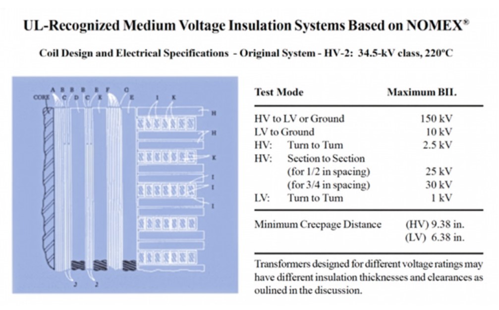
For critical dry-type transformer applications such as data centers, semiconductor plants, HV inverter transformers, the users often specify insulation thermal class of 180°C. But at the same time the insulating paper in class 220°C is required to ensure the highest reliability and safety. 220°C insulation system is also certified by UL up to 34,5 kV with 150 kV BIL and disk type windings.
4. Economic and social benefits
Operating cost for a year could be calculated to measure energy saving as follows:
B = Th×Ty×(Po + Pk×β^2)
Where:
B: Transformer power consumption, kWh
Th: operating hours in a year, 8760 h
Ty: operating period, 1 year
Po: no-load loss, kW
Pk: load loss, kW
β: load rate, 1.0 at 100%
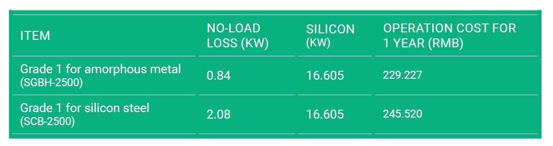
Losses stipulated by GB 20052-2022 “Power Transformer Energy Efficiency Allowable Values and Energy Efficiency Grades” [5] is in Table 2 for 2500 kVA dry-type transformer. The 2500 kVA, amorphous VPI transformer could save 10 862 kWh and 16 293 RMB a year when compared with silicon steel transformer. According to data released by the National Energy Administration of China, coal consumption for energy generation in 2020 is 0.305 kg/kWh, which generates carbon emission of 0.75 kg/kWh. It shows that amorphous VPI transformers can save 3318 kg of coal to reduce 8145 kg of carbon emissions every year.
CONCLUSION
Energy efficiency is a key solution for climate change since coal, oil and gas account for over 75% of global greenhouse gas emission. It implies that materials and technology in transformer production are important to generate less carbon emission due to less energy consumption at manufacturing and low losses in transformer operation.
VPI transformers with enhanced insulation systems and materials rated for 220°C could be one of user’s selection when they look for green energy and environmental protection. Additional benefits are fire safety, high reliability, compact size and resilience over climate change that fit well for requirements in transformer applications such as data centers, charging stations, distribution networks and inverter systems.
References
[1] ”Theory and Technology of Dry Power Trans former“, P113-P119, Lu Chang Bai, Liaoning Science and Technology Publishing House
[2] “Theory and Design of Special Transformer”, P93-P100, Cui Li Jun, Scientific and Technical Documentation Press
[3] “Application Technology of Amorphous Alloy Core Distribution Transformer“, P14-P16, Sheng Wang Xing, China Electric Power Press
[4] IEC 60076-12 “Power transformers – Part 12: Loading guide for dry type power transformers”, 2008
[5] ”Power Transformer Energy Efficiency Allowable Values and Energy Efficiency Grades” GB 20052-2020
Kacey Lee has experience in research and development of technology for electric insulation and transformers in global market since January 1986. His job experience includes Design Manager at LS Electric and application development leader at DuPont Korea. Currently he provides consulting services for businesses in transformers, motors and insulation materials

Radoslaw Szewczyk received his Master’s degree in Electrical Engineering at Åódź University of Technology in 1998. He works for DuPont™ Nomex® Energy Solutions in Poland as a Technical Service & Development Engineer. He supports transformer develop ments with application of Nomex® aramid electrical insulation. He is a member of IEC and CIGRE working groups.
Han Lu received his Ph.D. degree from Wuhan University. He is currently serving as the Chair man of CEEG Electric in China. Recognized as a Young Entrepreneur Leader in the Yangtze River Delta and a Leading New-generation Entrepreneur in Jiangsu Province, he is respon sible for the strategic planning and execution of the company’s research and development system.
Chengxiang Jin is a Senior Engineer specializing in electrical technology. He is en gaged in research and development related to transformer design, manufacturing, and processes in CEEG China.
Ning Li is a professor-level senior engineer. Her work in CEEG China primarily focuses on transformer product development, standardization, and intelligent manufacturing. She also serves as an expert member of the Jiangsu Association for Enterprise Technical Transformation and the Jiangsu Electrical Equipment Industrial Association.
This article was originally published in the October 2025 issue of the Advanced Insulation Soulutions: Condition Monitoring for a Safer Grid magazine.
View Magazine